When creating a prototype, the question of power supply often arises. Without a stabilized power supply, it is often impossible to power multiple setups simultaneously. This is why I propose a low-cost solution to power these microcontroller-based circuits. With this project, you will only need to power the board (via a transformer plug), and the board will be able to deliver a regulated voltage as well as a current of up to 2 amps!
By Romain Berthoule, on 01/04/2025

| Component | Quantity | Buy | |
|---|---|---|---|
| Power Supply Module | 1 | Contact Me | |
| Prototype to be powered | 1 | ||
| Multimeter | 1 |
| Software Name | Comment | |
|---|---|---|
| Kicad (or equivalent) | for circuit design | |
| TI Workbench | to simulate the circuit (specific needs) |
The primary objective is to create a small module that regulates voltage. This voltage must be set to 3.3V to power a circuit. Additionally, the regulator must be able to deliver sufficient current to power a significant load. Thus, these characteristics are:
The project begins with the design of the circuit. At this stage, you can visit the Texas Instruments website (TI Workbench) to simulate your circuit based on your criteria (e.g., voltage, current).
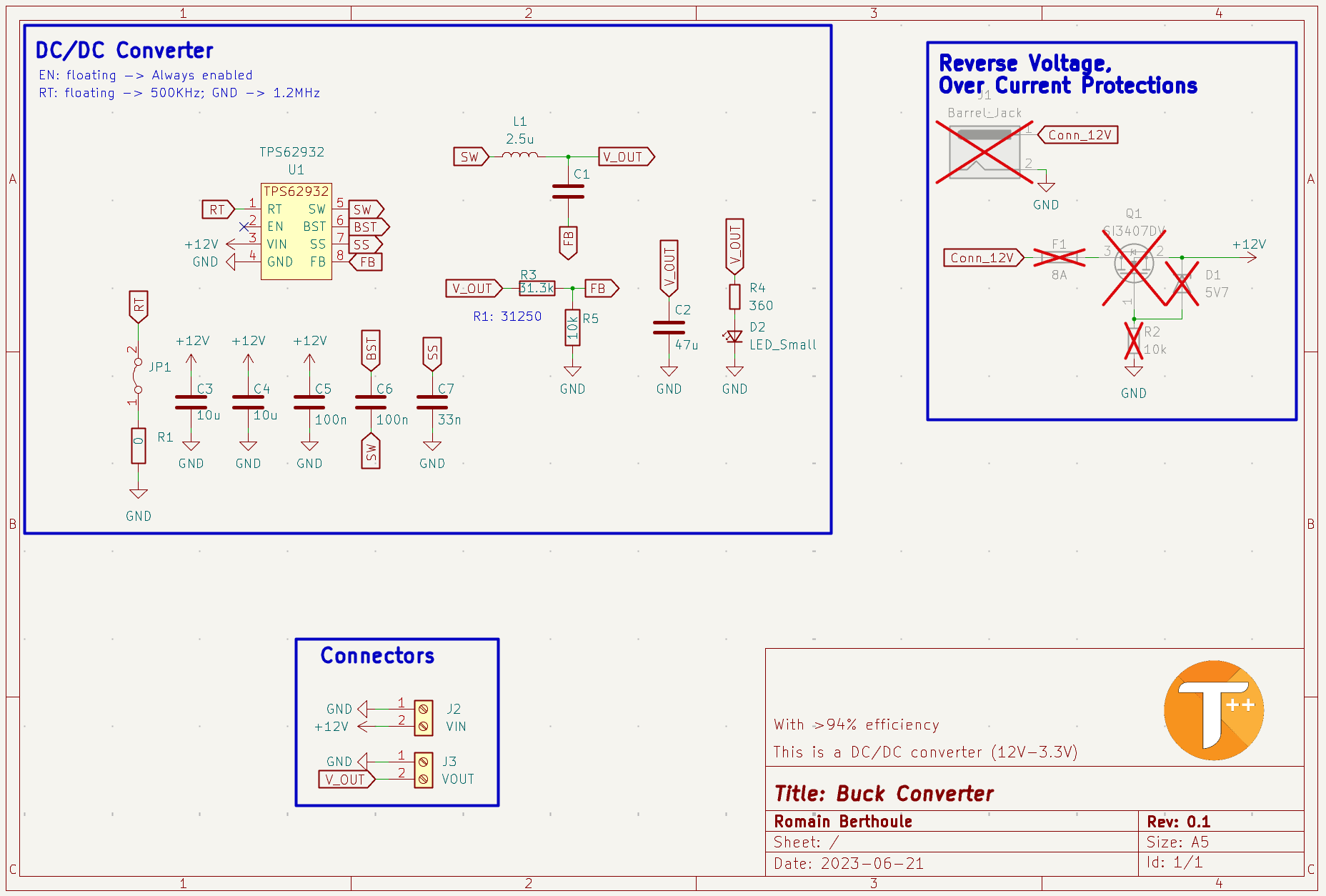
Here, I used the TPS62932, a recent Buck-type converter. The main advantage of these converters is their conversion efficiency. Indeed, compared to linear converters, the Buck circuit performs modulation to lower the voltage, such as PFM (Pulse Frequency Modulation), which is essentially PWM. In contrast, a linear regulator acts as a large variable resistor to lower the output voltage. The linear regulator is not efficient because the conversion induces thermal loss.
In my diagram, most of the capacitors are decoupling capacitors. They serve as energy reservoirs, which they will deliver if there is a consumption spike in the circuit. Thus, they prevent current oscillations (voltage ripple in English). The inductor smooths the current. In this diagram, the circuit has been configured to deliver an output voltage of 3.3V using a voltage divider bridge (R3, R5). Finally, it is possible to adjust the converter's modulation frequency according to needs, thanks to the resistance value R1.
Before diving into routing, it is essential to consider a few parameters. The most important is the size of the components. Depending on who produces this PCB, you will need to consider their constraints. Here, I will have it manufactured by a Chinese manufacturer who accepts components as small as 0402. Therefore, I have no limitations in this regard. However, I chose 1206 packages for the capacitors to solder them by hand. After defining the component footprints in Kicad, I obtained a circuit like this:
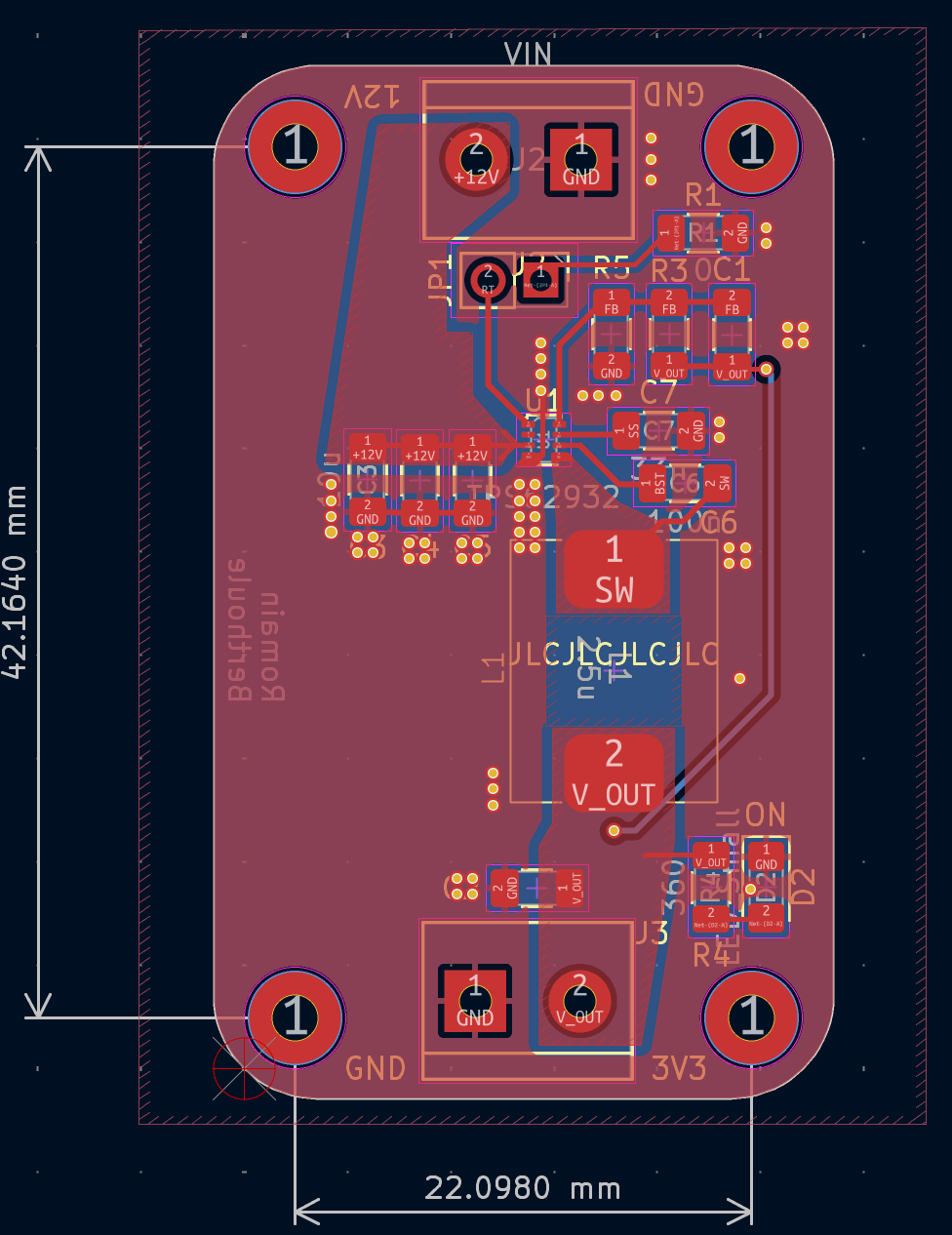
Several points are important to highlight in this routing. First, the traces are more or less thick depending on the current flowing through them. This helps to avoid creating unnecessary resistance. Additionally, I placed a significant number of vias to reduce inductance between ground planes and dissipate heat more quickly. It is also essential to place components as close as possible to the integrated circuit to reduce the size of the current return loop and not degrade the circuit's operation. Once the routing is complete and the components are selected (BOM), the circuit order can be placed, followed by assembly.
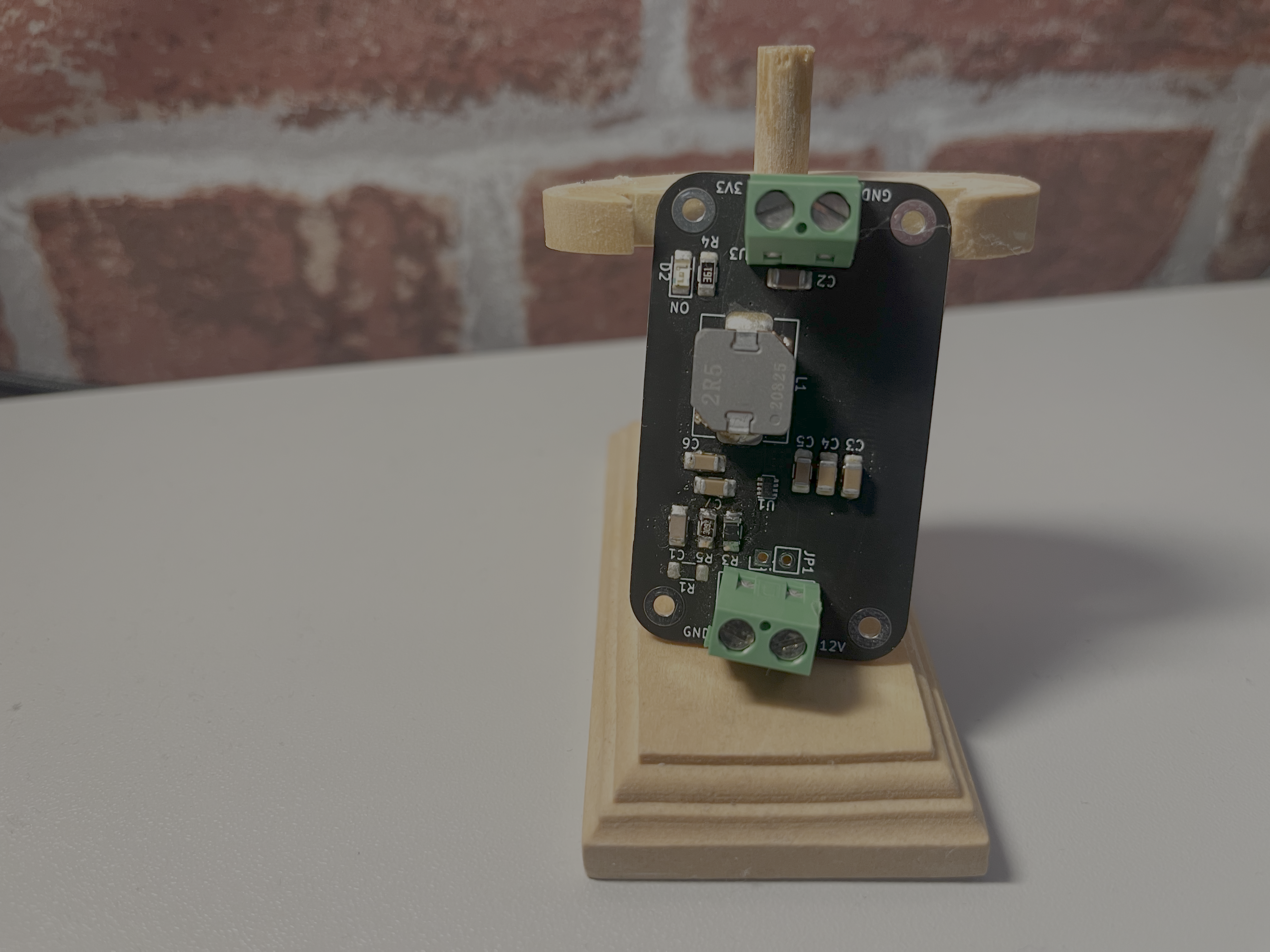
For this crucial step, I recommend having it done by the PCB manufacturer (especially if the components are small). Otherwise, if you do it yourself, you will need solder paste, a solder mask (stencil), and a soldering station (hot plate or oven). To begin, align the solder mask with your PCB, then apply this paste to the holes of this mask using a squeegee (or equivalent). Ensure the application is uniform. Next, position the components (using tweezers) and then "bake" the PCB to melt the solder paste. There you go! The PCB is ready to be tested. It is possible that these operations may not go as planned, and in that case, repair operations are necessary. Finally, we obtain our voltage conversion module:
The unit price of the board is $1.02, and the components cost $9 (excluding shipping). This makes the module a fairly high-performance power supply for only $10.
Now, it is necessary to test the circuit and verify that it meets the requirements.
It is possible to make improvements to this project to make it more modular, for example. Thus, it is possible to replace the PWM frequency adjustment resistor with a potentiometer. This will optimize efficiency based on usage. In the same spirit, it is possible to modify the voltage divider bridge (add another potentiometer) to adjust the output voltage.
Additionally, this circuit is not protected (overvoltage, undervoltage, short circuit ON/OFF); these are ideas to implement based on needs.
Share your opinion or contribute to project improvements by sharing your feedback!